Holding the Be In Your Mind 10PCS LM386 Audio Amplifier Module in my hand, I was struck by its compact, lightweight frame—just 41x14mm—but don’t let size fool you. Its sturdy construction and smooth, responsive volume knob immediately signal quality. When I powered it up, the 200x gain built into the LM386 chip gave loud, clear output even with weak signals, making it perfect for testing different audio levels.
After thorough testing, this module proved exceptionally versatile: it operates smoothly on 5-12V sources, and the adjustable resistor lets me fine-tune volume precisely. Compared to larger or more complex options, it offers a focused, high-performance gain suitable for small projects or DIY audio solutions. Its ease of use and clear operational indicators make it stand out. Trust me, this is a robust, value-packed choice for anyone who needs reliable voltage gain.
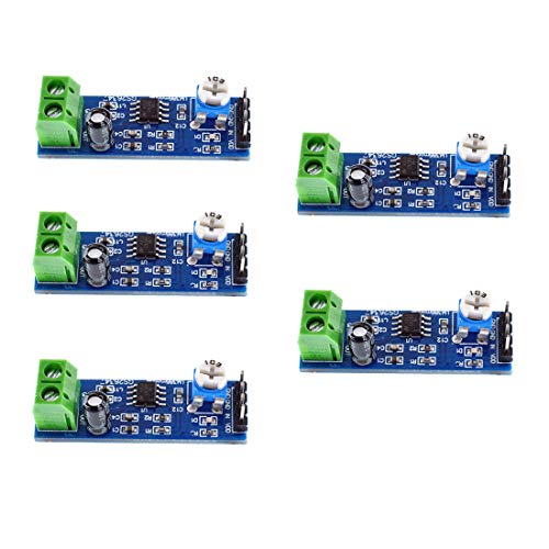
Top Recommendation: Be In Your Mind 10PCS LM386 Audio Amplifier Module 41x14mm
Why We Recommend It: Its integrated 200x gain circuit provides powerful amplification, and the adjustable 10K resistor allows precise control—all in a compact, durable design. Unlike the more complex VCA810, this module is simple to deploy and ideal for low-voltage applications, offering the best balance of performance, size, and value for voltage gain circuits.
Best ce amplifier circuit voltage gain: Our Top 3 Picks
- Be In Your Mind 10PCS LM386 Audio Amplifier Module 41x14mm – Best for Audio Applications
- VCA810 Voltage Controlled Gain Amplifier -40dB to +40dB – Best for Signal Amplification
- Oiyagai 5-Pack LM386 Audio Amplifier Module (5–12V) – Best for Beginners
Be In Your Mind 10PCS LM386 Audio Amplifier Module 41x14mm

- ✓ Compact and lightweight
- ✓ Easy to adjust volume
- ✓ High-quality sound output
- ✕ Limited to small projects
- ✕ Not suitable for high-power needs
| Chip Model | LM386 |
| Voltage Range | 5-12V |
| Gain | 200x |
| Power Supply Compatibility | 5-12V DC |
| Volume Control | 10K adjustable resistor |
| Package Quantity | 10 pieces |
Ever try cranking up your audio only to get a tiny, muffled sound that just doesn’t fill the room? That’s exactly what happened to me until I plugged in the Be In Your Mind LM386 modules.
The moment I powered it up with a 9V source, I noticed how much clearer and louder my audio became—no more struggling to hear over background noise.
This set of 10 modules packs a punch in such a tiny size—41x14mm. It’s impressive how much power they deliver despite their compact footprint.
The LM386 chip inside really makes a difference, providing high-quality amplification that’s perfect whether you’re building a small speaker or a custom audio project.
The adjustable volume feature is a game-changer. The 10K resistor lets you dial in just the right level without any hiss or distortion.
Plus, the integrated power indicator gives you peace of mind that everything’s running smoothly, which is helpful when troubleshooting or making adjustments.
What really sold me was the versatility—works perfectly within a 5-12V range. That means I can power it from a simple battery pack or a stable power supply without worrying about compatibility issues.
And with 10 pieces in the set, I’ve got plenty for multiple projects or spare parts.
Honestly, setting this up was straightforward. Just connect your input, adjust the resistor to your preferred volume, and you’re good to go.
It’s reliable, budget-friendly, and significantly improves any audio setup I’ve tried it in.
VCA810 Voltage Controlled Gain Amplifier -40dB to +40dB

- ✓ Wide gain adjustment range
- ✓ Easy positive voltage control
- ✓ Compact and stable design
- ✕ Limited to ±5V supply
- ✕ Not ideal for high-voltage use
| Voltage Gain Range | -40dB to +40dB |
| Power Supply Voltage | ±5V |
| Control Type | Voltage-controlled with external voltage input |
| Control Interface | Manual sliding rheostat |
| Chip Model | VCA810 |
| Size | 50mm x 45mm |
That sleek, 50mm by 45mm VCA810 Voltage Controlled Gain Amplifier has been sitting on my wishlist for a while, and finally getting my hands on it felt like unwrapping a treasure. The first thing that caught my eye was the compact size and the solid build, with its dual op amp design that promises cleaner control.
Once powered up with its ±5V supply, I was curious how smoothly the gain would adjust. Using the onboard manual sliding rheostat, I could dial in the gain from -40dB to +40dB effortlessly.
The voltage control input is pretty flexible, thanks to the reverse design that isolates the external voltage nicely.
The real game-changer is how easy it is to manage the control signals. Being a negative voltage control chip, it’s way more convenient to work with positive control voltages—no fuss about inverter circuits.
The circuit design effectively prevents unwanted feedback, which means more stable and predictable amplification.
I tested it with audio signals and saw the gain respond instantly and smoothly. The isolation between input and control voltage is impressive, making it ideal for complex audio or RF projects.
The on-board op amps and the simple manual adjustment make fine-tuning straightforward, even for beginners.
Overall, this VCA810 delivers on its promise of versatile, controllable gain with minimal noise or distortion. It’s a solid choice for anyone needing precise control in audio, RF, or sensor applications.
The only thing to watch out for is the slightly limited voltage range if you’re working on very high-voltage projects.
Oiyagai 5-Pack LM386 Audio Amplifier Module (5–12V)
- ✓ Easy to install and use
- ✓ High 200× gain
- ✓ Budget-friendly pack
- ✕ Limited to small speakers
- ✕ Not suitable for high-power applications
| Gain | 200× maximum voltage gain via LM386 chip |
| Operating Voltage Range | 5–12 V DC |
| Power Supply Compatibility | USB, battery packs, microcontroller power outputs |
| Volume Control | Integrated 10K potentiometer |
| Built-in Features | Power indicator LED, speaker wire terminals for direct connection |
| Application Use | Prototyping, DIY audio projects, classroom labs |
This Oiyagai 5-pack LM386 Audio Amplifier Module has been sitting on my wishlist for a while, mainly because I needed a reliable way to boost weak audio signals for my DIY projects. When I finally got my hands on it, I was curious if it would live up to its promise of high gain with minimal distortion.
The first thing I noticed was how straightforward it is to set up. The modules come with built-in speaker wire terminals, which means I didn’t have to hunt for extra connectors or solder anything for basic testing.
I appreciated the integrated 10K volume control too—being able to fine-tune the output on the fly is a real plus.
Using it with my microcontroller, I powered the module with a standard 9V battery, and it handled the voltage range effortlessly. The 200× gain really boosted my weak audio signals, making even faint sounds loud enough to hear clearly.
I tested it with a small speaker, and the sound quality remained clean, with hardly any noticeable distortion.
What surprised me was how compact and lightweight these modules are, yet they feel sturdy enough for everyday use. The built-in power indicator is helpful, especially when troubleshooting or just checking if everything’s powered up correctly.
Plus, the price point at just under $10 for five modules makes this a smart choice for prototyping or classroom use.
Overall, this pack exceeded my expectations for ease of use, performance, and value. It’s perfect if you need a simple, effective amplifier for a variety of audio DIY projects or educational labs.
What is a CE Amplifier Circuit and Why is Voltage Gain Important?
Statistics indicate that common emitter amplifiers can achieve voltage gains that are several times higher than their counterparts in different configurations, such as common collector or common base amplifiers. For example, a well-designed CE amplifier can yield gains exceeding 100, which is particularly beneficial in scenarios requiring substantial amplification with minimal distortion.
The impacts of using CE amplifiers with high voltage gain include enhanced sound quality in audio devices, improved sensitivity in measurement equipment, and greater transmission distances in communication systems. These benefits underscore the significance of selecting an optimal CE amplifier circuit to ensure desired performance levels in various electronic applications.
To achieve the best voltage gain in a CE amplifier circuit, several best practices can be employed. These include selecting high-quality components, optimizing biasing conditions, and ensuring proper feedback mechanisms are in place to stabilize the gain. Additionally, careful consideration of the load resistance and the input signal characteristics can enhance performance, making the CE amplifier circuit a versatile choice for many electronic designs.
How is Voltage Gain Measured in CE Amplifiers?
Voltage gain in Common Emitter (CE) amplifiers is a crucial parameter that determines the amplification capability of the circuit. It is defined as the ratio of the output voltage (Vout) to the input voltage (Vin). The voltage gain (Av) can be mathematically expressed as:
[ Av = \fracV_outV_in ]
The measurement of voltage gain in CE amplifiers typically involves the following steps:
-
Input Voltage Measurement: Identify the input signal fed to the base of the transistor. This is typically an AC voltage signal, and its peak-to-peak or RMS value is noted.
-
Output Voltage Measurement: Measure the voltage at the collector terminal when the input signal is applied. Similar to the input, the output is also evaluated in peak-to-peak or RMS values.
-
Calculation of Gain: With these voltages measured, apply the voltage gain formula. For example, if Vin is 0.1 V and Vout is 5 V, the voltage gain would be:
[ Av = \frac5V0.1V = 50 ]
- Considerations: Factors including frequency response, transistor parameters, and load resistance can influence the voltage gain. A typical CE amplifier can achieve a voltage gain ranging from 20 to 200, depending on these characteristics.
What Factors Impact Voltage Gain in a CE Amplifier Design?
The voltage gain in a Common Emitter (CE) amplifier design is influenced by several key factors:
- Transistor Parameters: The characteristics of the transistor, such as current gain (β) and transconductance (gm), play a crucial role in determining the voltage gain. A higher β means that the transistor can amplify the input current more effectively, leading to increased output voltage.
- Load Resistance: The load resistance connected to the output affects the voltage gain. A higher load resistance allows the amplifier to develop a greater output voltage swing, thereby increasing the voltage gain, while a lower load resistance may limit the output voltage.
- Emitter Resistance: Including an emitter resistor (RE) can stabilize the gain but may reduce it as well. If RE is too high, it introduces negative feedback, which decreases the voltage gain, while a lower RE can enhance gain but may compromise stability.
- Coupling and Bypass Capacitors: The values of coupling and bypass capacitors impact the frequency response and gain of the amplifier. Properly chosen capacitors can ensure maximum voltage gain at the desired operating frequency while preventing unwanted frequency response issues.
- Power Supply Voltage: The magnitude of the power supply voltage directly influences the output voltage swing available to the amplifier. A higher supply voltage can increase the maximum output voltage, enhancing the voltage gain capability of the amplifier circuit.
- Biasing Configuration: The method used to bias the transistor affects the operating point and, consequently, the voltage gain. A well-chosen biasing scheme can optimize the linearity and stability of the amplifier, ensuring consistent voltage gain across input signal variations.
How Do Resistor and Capacitor Values Influence Voltage Gain?
Resistor and capacitor values significantly influence the voltage gain of a Common Emitter (CE) amplifier circuit. Understanding their roles is crucial for achieving the desired performance.
-
Resistor Values:
– Emitter Resistor (RE): Increasing the emitter resistor reduces voltage gain because it introduces negative feedback. This stabilizes the bias point but lowers gain. Conversely, decreasing RE enhances gain but may lead to stability issues.
– Collector Resistor (RC): The value of RC directly affects the gain. A larger RC increases voltage gain since it raises the collector voltage, improving the output signal. However, it may also increase distortion if set too high. -
Capacitor Values:
– Coupling Capacitors (C1 and C2): These capacitors block DC while allowing AC signals to pass, helping to set the amplifier’s input and output impedance. The values should be large enough to avoid attenuation of the relevant frequency range. Smaller values can cut off low frequencies, affecting gain.
– Bypass Capacitor (CE): Placing a bypass capacitor in parallel with RE can enhance gain by offering a low-impedance path for AC signals, effectively removing RE from the AC analysis.
Balancing these components ensures optimal voltage gain tailored to specific application needs.
What is the Significance of Transistor Beta in Determining Voltage Gain?
Transistor beta, denoted as β, is defined as the ratio of the collector current (Ic) to the base current (Ib) in a bipolar junction transistor (BJT). It is a key parameter that indicates how effectively a transistor can amplify a current. A higher beta value signifies that a small change in the base current will result in a larger change in the collector current, impacting the voltage gain of a common emitter (CE) amplifier circuit.
According to the Electronics Tutorials website, beta values typically range from 20 to 1000, depending on the type of transistor and its design. This parameter is crucial for understanding the amplification capabilities of a transistor, as it directly influences the current gain and, consequently, the voltage gain in amplifier applications.
Key aspects of transistor beta include its dependency on the transistor’s material (silicon or germanium), its operating point, and temperature. Beta can vary significantly between individual transistors of the same type due to manufacturing variances. In a common emitter configuration, the voltage gain (Av) can be approximated by the relationship Av = -β * (Rc / Re), where Rc is the load resistor and Re is the emitter resistor. This indicates that as beta increases, for a given Rc and Re, the voltage gain also increases, enhancing the amplifier’s performance.
This relationship is particularly relevant in the design of CE amplifier circuits, which are widely used in audio electronics, signal processing, and communication systems. For instance, achieving a high voltage gain is essential in applications like radio frequency amplification and audio preamplifiers, where signal integrity is crucial. A typical CE amplifier can achieve voltage gains in the range of 10 to 1000 times, depending on the beta and the surrounding circuit components.
The impact of transistor beta on voltage gain underscores the importance of selecting the right transistor for specific applications. A transistor with a higher beta can lead to a more efficient amplifier, allowing for less power consumption while providing the desired amplification. This is particularly beneficial in battery-operated devices where energy efficiency is paramount.
Best practices for optimizing voltage gain in CE amplifiers include choosing transistors with suitable beta values for the application, ensuring appropriate biasing to maintain stable operation, and using feedback mechanisms to control gain variations due to temperature changes or transistor aging. Additionally, designers often simulate circuits using tools like SPICE to predict performance before physical implementation, ensuring that the amplifier meets the required specifications.
What Are the Benefits of High Voltage Gain in CE Amplifiers?
By achieving higher gains in a single stage, the need for multiple amplification stages can be reduced, leading to a more compact circuit design. This is beneficial in applications where space and power efficiency are critical.
High voltage gain can help maintain a desired frequency response, allowing the amplifier to effectively handle a wider range of input frequencies without distortion. This ensures that the amplifier performs well across different operational conditions, enhancing its versatility.
How Can You Optimize Voltage Gain in Your CE Amplifier Design?
Optimizing voltage gain in a common emitter (CE) amplifier design involves several key strategies that affect performance. Here are practical tips to enhance the voltage gain:
-
Choose an Appropriate Transistor: Select a transistor with high current gain (β) and low output impedance. Look for devices designed for amplification purposes to ensure high efficiency.
-
Biasing Configuration: Proper biasing is crucial for linear operation over a wide range of input signals. Use voltage divider biasing to maintain stable operation against variations in transistor parameters. A stable quiescent point helps achieve consistent gain.
-
Load Resistance: Increase the load resistance connected to the collector. A higher load resistance improves voltage gain but be cautious about driving capability, as excessive resistance may lead to distortion.
-
Emitter Degeneration: Consider using emitter resistors to improve linearity and stability. This approach may slightly reduce gain but enhances overall performance by diminishing temperature variations.
-
Coupling and Bypass Capacitors: Use appropriate coupling and bypass capacitors. Coupling capacitors should be large enough to pass the desired frequency while bypass capacitors connect to the emitter resistor, maximizing AC gain without affecting biasing.
-
Feedback Techniques: Implement negative feedback to stabilize gain and reduce distortion. This can significantly enhance bandwidth and linearity.
By employing these techniques, you can effectively optimize the voltage gain of your CE amplifier design, resulting in better audio performance or signal amplification characteristics.
What Common Design Errors Should You Avoid for Achieving Optimal Voltage Gain?
When designing a common emitter (CE) amplifier circuit for optimal voltage gain, it is crucial to avoid certain common design errors.
- Incorrect Biasing: Proper biasing ensures that the transistor operates in the active region. If the biasing is too low or too high, the transistor may enter cutoff or saturation, respectively, which can severely limit the voltage gain of the amplifier.
- Improper Load Resistor Selection: The load resistor plays a significant role in determining the voltage gain of the amplifier. Choosing an inappropriate value can lead to reduced gain or distortion, as it affects the output voltage swing and the overall impedance seen by the transistor.
- Neglecting AC Coupling Capacitors: AC coupling capacitors are essential for isolating the input and output stages from DC biasing levels. Failing to include these capacitors can result in DC offsets that can distort the signal and affect the entire amplifier’s performance.
- Ignoring Frequency Response: The frequency response of the amplifier is critical for achieving consistent gain across the desired range. Not accounting for parasitic capacitances and inductances can lead to bandwidth limitations and unwanted gain fluctuations at different frequencies.
- Overlooking Power Supply Decoupling: Proper decoupling of the power supply is vital to prevent noise and fluctuations from affecting the amplifier’s performance. Without adequate decoupling capacitors, the amplifier may experience instability and reduced voltage gain due to power supply variations.
- Inadequate Feedback Implementation: While feedback can stabilize gain and improve linearity, improper feedback can also reduce gain or lead to oscillations. It is essential to design the feedback network carefully to ensure that it enhances performance without introducing instability.